18/11/2020

More examples of the OST Morse Box

See the original description of the OST Morse Box here.

And the nice cabinet made by my co-author Gilbert, ONL12523,  here.

A few more people sent me pictures of their version.

This one was built by Wil, ON6EO.

The frame is made from pieces of PCB, the cover was bent from a piece of sheet metal (the cover from a PC, which was already painted). 

The other outer surfaces were spray painted. Doesn't it look professional ?


Completed Morse Box


Insinde view from the front


Inside view from the back


This is a "quick and dirty" build by our Morse Teacher Aimé, ON4AIM
Only the three knobs on the potentiometers are still missing, but the Morse Box is operational.


Four more Morse Boxes were built by Jos, ON6WJ and his friends. Jos sent me this picture, with two of those already boxed and "personalized" by Luc, ON4AAQ, nice work !


Have YOU built the OST Morse Box?

Please send us some pictures, and we can add them to our gallery!

To be continued ...

73,

Luc, ON7DQ
(e-mail address is on QRZ.com)

06/10/2020

Testing the ATU-100


After weeks of rain, today we had a nice sunny day, so time to get out to a local park and set up my KX3, with the internal ATU disabled, and test the ATU-100 (See my report on building it here).

I set up my favourite SOTA antenna, a 9.15m endfed with 4m CP, and a 9:1 UNUN, coax 3.5m RG-58. The antenna was sloping from abt. 5m to 1m above ground as you can see in the picture.


The KX3 tunes this antenna without any problems from 80m to 6m, SWR = 1 everywhere, but of course, the efficiency will vary considerably.  

I tried to tune the antenna with the ATU-100 on all bands from 80m to 6m.
I double checked the SWR with a Hansen SWR3S SWR/PWR meter, since the SWR meter in the KX3 is rather coarse to get a good reading.


At first, the ATU wouldn't work in AUTO mode, so I set it to MANUAL, and then got it tuning by pressing the red TUNE button each time I changed bands.
Here the results.


The small differences in measured SWR are acceptable I think.
SWR is measured on a different spot along the transmission line, and there may be a slight loss in the connecting cable.

Next, I put the tuner back in AUTO mode, and did a few band changes ... and believe it or not, it worked like a charm !

I went back to 40m ==> 1.21 , then to 20m ==> 1.05, then 15m ==> 1.17, then 10m ==> 1.16, and back to 40m ==> again 1.21, all within a few seconds of transmitting, and without touching any button.

During the whole afternoon, the average current consumption was 30 to 40 mA. And I could not hear the strange noises as reported on the SOTA Reflector by Ed, DD5LP.


[Note: the laptop case contains my 4-band 50W amplifier (the so called Chinese DIY Kits 70W Amp), LiPo battery,  another ATU  (an LDG Z100) and the Hansen SWR meter]

Ok, time for another test, QRP !

I intended to use this tuner for my QCX rigs (40m and 20m models), but for this test I just put the KX3 at 5W.

But now comes the disappointment: the ATU-100 as built does not tune with only 5W.

I have to study the manual and some websites, I may have to put a few more windings on the Tandem Match to increase its sensitivty.

So nothing else to do than tune up with 15W, and then reduce the power to 5W QRP.

The sun was still shining, so I tried to make a few QSO's. Unfortunately, no SOTA stations in Europe were spotted. Here the log of what I worked, and powers used.


* The bad report I got from EI7JN was because I had put the ATU in AUTO mode again, and halfway each transmission it started retuning, but then stopped at a bad SWR, and as a result the KX3 folded back to only 5W. Even when tuning manually then, it was difficult to get a good tuning, since the KX3 refused to put out more than 5W. 

By 17:30 local time, I was getting cold and it was time to go home ...


CONCLUSION

From these short tests, I could conclude the following:

Does it work ?
Yes, sometimes, if you're lucky, and if you have more than 10W, so as it is, it's not suited useful for QRP.

Is it reliable ?
Hmmm, I would have to do some more testing. I don't think I would trust it as my only option.
For SOTA, I will rely on the tuner in the KX3 for sure. And for the QCX rigs, i will probably stick to the tuned antenna's I was using before (link dipole, half wave endfed or ground plane vertical).

So all in all, a nice little tuner, and it can fulfill some purposes ... but don't expect more from it than what you paid for ...
If I find better results after more testing, I'll let you all know.

73,

Luc ON7DQ


23/09/2020

Building an ATU-100 (N7DDC)


EDIT (November 2025) : I built a second ATU-100 in a different case, and also wrote a report about it. You can find here.


I won't make a full report of my build , since all information on this autotuner is available online.
This is the github page where you can find it all.
Some nice descriptions can be found by Googling ATU-100.

And visit these pages by R0AEK with some very helpful information (in Russian, but Google does a decent translation). There are 4 parts.

So here just some pictures of what I did, from the package arriving from China (in 11 day's, that was quick !), to the final result.

The parts arrived in a nice plastic box, and then in some plastic bags.

The SMD's all pre-soldered.


The SWR bridge


All coils ready, with some other components.


Adding the 15 relay's.


Winding the tandem match was the hardest part. TIP : I removed a few strands from the RG58 center conductor to make it fit the holes in the PCB.


All parts of the case ready to assemble.


Detail of the front panel


Back panel


Back panel inside.


Boxed it !


Making the connections to the board is not complicated, see markings on the main PCB.


GND and + is for the 12V DC power supply or battery. 
GND and B is for the big TUNE button
On the 5 pin connector, only 4 pins are used to connect the OLED display:
VCC  goes to VCC on the display
GND              GND
DAT               SDA
CLK               SCL

Finally there are two optional buttons, they connect to two pads on the underside of the PCB, the other side of the buttons goes to GND of course.
B1 is the AUTO button (it shows as a DOT on the display).
B2 is the BYPASS button (it shows as an UNDERSCORE on the display).
 
This pictures show clearly where those pads are, but be careful with static when soldering, the pads are directly connected to two CPU pins. It is advised to put a 100 nF capacitor over each of those buttons, to avoid RF getting directly into the CPU. 


Almost finished


The last step was making a nice cover. I used the top cover from an old Macbook Pro laptop, and was able to save the "Apple" ... hi.

Adding a high brightness LED, using only an extra 5 mA to light the Apple logo, this is the result !


I only did a short test on my home antenna, and all seemed to work ok. 

More extensive testing to follow during my SOTA or other /P activities ...

UPDATE : to be used with a QRP trransceiver, I did not change the winding on the SWR bridge, but only changed cell 05 in the EEPROM to a value of 01 (minimum tuning power 1 Watt).
I found this info in a video by MW0SAW, watch it here.
Note: the video is a bit confusing, since it treats the ATU-100 (EXT), ATU-100 Pro and the ATU-QRP 40 (all in the same video !).
These are my actual EEPROM values:


73,
Luc - ON7DQ

22/08/2020

Building the DIY Kits 70W Linear Amplifier


Introduction

 Like many other hams, I couldn't resist ordering a Chinese kit for a 70W amplifier for under 20$!
This kit comes without any documentation, but luckily some good people have done all the work for us.

First there is this excellent description by PD7MAA that you MUST read. And in this page you will find the link to a very extensive description by OE1CGS , including a simple mod to substantially improve the input SWR. Most of that text is in German, but there is an abbreviated English text here.
Finally, DK9JC did some tests on this amp, and his report has many pictures.

I won't go into the circuit diagram and other details, you'll find it all on the sites above. Here just some pictures and a description of how my version turned out.

I wanted to use it first of all with my two QCX rigs, for the QRP-Labs QCX QRO Challenge
So I built two LPF, one for 40m and one for 20m, with the values found on the PD7MAA site (and are also used in the excellent 50W PA by QRP Labs).

Knowing that I have used my QCX rigs on "one band down" without much degradation, those filters are also good for 60m and 30m. So I would end up with a 4 band amplifier.

And yes, I know that we can only put out 15W ERP on 60m, but that may be what you get if you put 50W in a compromise antenna ... right ? ;-)
Anyway, I did work EA8 with an unmodified 40m QCX on 60M one day, and have made several QSO's on 30m with my 20m set. All with a slightly reduced power of 4 Watts, so who needs an amplifier?

First test

First, I wanted to do some tests, and I built a kind of breadboard setup, which you can see below. 
After some measurements, I concluded that 2W drive power was about the right level.
Problem: I can reduce the power in my KX3 to 2W, but not so easily in the two QCX rigs which give 5W ... that's 4 dB too much power. On a bench supply, you can reduce the supply voltage, but when operating from batteries it may not be that easy.
So for those rigs, I added the option to insert a 4dB attenuator. 
I didn't want to make it too complicated, so the 4dB attenuator stays in line for RX, while it should only serve in TX mode ... I know! Maybe I will change that in the future or in a next (re)-build.


In the picture, left to right:
The two low-pass filters, the amplifier module with heatsink and fan (the CPU cooler from an old PC), a PTT switch to manually put the amp in TX mode, and the 4dB attenuator for QCX use.
All my tests were done at Vcc = 12V. I know you can get way more power at higher voltages, but I want to use this amp on batteries, so 12V it had to be. 

All worked well and I got over 60W on 40m , and around 50W on 20m.
After those tests, I did the mod by OE1CGS (see link above), by adding a 22Ω/2W resistor over the secundary of the input transformer T1 (see picture).

This brings the input SWR down from 5 to just 1.1. Quite an improvement, but the drawabck is that you loose a bit of output power. Now I would get 45W and 36W out. Still good enough for me ...

Now you may have noticed that I also have a KX3, which gives 15W from 80m to 20m, so why an amplifier whivh only gives a maximum gain of at most 5 dB ?

The problem with those 15W is that the KX3 needs a higher supply voltage for that, and when operating in a hot climate like in EA7, it will quickly heat up and then will switch back to 10W or even 5W. Adding a black heatsink will not help much in a hot climate. Adding a fan does help, but that is then another item to carry ...

Running my KX3 at only 2W will avoid the heating problems, and I may even run it on its' internal batteries for quite a while.

Putting it in a box

I tried to make it as small and light as I could, and ended up with a plastic modem case. Total weight is only 560 g (excluding batteries , hi).


I cut the breadboard  in tghree, saving the LPF board and attenuator board.

The amplifier module was mounted upside down on some spacers, so that the heatsink protrudes on the top.
I added a connector for PTT control, compatible with the KX3 control cable, and removed the switch.
I still have to modify the QCX rigs for PTT control, but that needs only one resistor and an extra 3.5 mm connector.

This is the back panel.


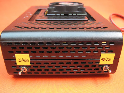
This is the side with the two switches for the LPF selection. Of course both switches must be on the correct position. I didn't want to put input and output on the same switch to avoid unwanted copupling, and maybe causiong oscillation.


And this was the end result


And here a view of the amplifier in use on a SOTA activation (2/9/2020 on ON/ON-027).
KX3 > Amplifier > Z-100 Autotuner. The setup was powered from a 12V/17Ah gel cell.

The Z-100 is to be replaced by the smaller ATU-100, another Chinese kit, which I described here:
Building the ATU-100


Measurements

I was also curious if the harmonics were within spec, so I used a Siglent spectrum analyser and 45 dB of attenuators in line, and at 2W input to the amplifier, I got the following results (click on the graphs to view details):

40m, mode CW, 7.033 MHz, Pout = 45W


Not a harmonic in sight, but if there are any, how big are they ?
This analyzer has a "harmonics test" mode, which instantly shows the level of all harmonics, related to the carrier power. All harmonics are more than 56 dB below carrier, so it looks very good.


The same for 20m, mode CW , TX 14.062 MHz, Pout = 36W


Here, the 3rd and 5th harmonic are just visible. The analysis shows that  they are still more than 45.6 dB below carrier, so still acceptable.

Is this "linear" really linear?

I did not make any real measurements (yet), but just tried the amplifier on the air in SSB mode during my SOTA activation. I asked several people who gave me a 59 report, if they heard anything special, any distortion or such ... and none of them could hear anything bad ... so far, so good.

I suppose it doesn't behave like an expensive "professional" amplifier, but we"re only "amateurs" after all ... 

If I ever get to make real measurements of the linearity, I'll update my post.

And now for real ...

After I boxed the amplifier, I did some brief test transmissions (3x CQ RBN on each band), and checked RBN for the results. See for yourself ... not bad eh ?


Conclusion

I'm quite satisfied with the result of this cheap amplifier. Total cost, with the LPF ringcores I had to buy, the rest being "free" stuff from my junk box, was under 20$.
I can use it on 4 bands, with both my KX3 and my two QCX rigs, delivering some 40-ish watts of power. Nice !

If you found anything useful in this report, let me know !

73,
Luc - ON7DQ 


31/07/2020

My IC-7300 "Big Controller" (part 2)


The Wiring ...

I finally found some time to continue working on this project.
See part 1 here

I have not drawn a complete wiring diagram because some things may change during the programming, after which I can make a final diagram.

So I'll just describe what I did in text form.


(source https://store.arduino.cc/arduino-mega-2560-rev3)


I used an Arduino Mega 2560, see pinout above.
Part of this project can probably also be made with an Arduino UNO, or even a Nano.
Just change the pins and change the code accordingly and see how far you get ...

If you need more pins for buttons, you can apply the analog port trick: add up to 5 buttons on one analog pin with a resistor network.
(see https://wiki.dfrobot.com/Arduino_LCD_KeyPad_Shield__SKU__DFR0009_ ) 

The TFT display can be changed for a simpler I²C controlled LCD display to save some wires and memory.

Also, I didn't use the extra hardware serial ports on the Mega, but I used SoftwareSerial, so the code should work on the UNO and Nano as well.
The only problem will be that you can't use a rotary encoder AND a SoftwareSerial port at the same time, since both need the interrupt pins, and the UNO/Nano only have two of those (D2 and D3).
So you will have to make a menu with some buttons for navigating. See this example:
https://educ8s.tv/arduino-nokia-5110-menu/


Now here is what I wired so far ...

First come all the pushbuttons:

4 BIG Memory buttons (short press = once, long press = repeat)

M1 <> A11          Send MEM1
M2 <> A12          Send MEM2
M3 <> A13          Send MEM3
M4 <> A14          Send MEM4

I will probably change these, as I can only send the VOICE memories via CI-V command.
It's a shame that Icom didn't provide commands for the CW/RTTY memories!
One solution is to mimic the resistor network at MIC pin 3, and use transistors to key them, like used by ON7EQ in his Arduino memory keyer.
(see https://www.qsl.net/on7eq/en/ under "Projects": ARDUINO ICOM Auto Keyer)

8 SMALL pushbuttons

B1 <> D31           Cycle TX POWER : 5W > 10W > 50W > 100W (levels settable via menu)
B2 <> D32           TUNE (put rig in mode CW , set power to 5W* as long as button is
                             pressed, then reset to previous MODE and POWER).
                             * Tuning power settable via menu.
B3 <> D33           BAND DOWN
B4 <> D34           BAND UP
B5 <> D35           TOGGLE USB AF <> IF
B6 <> D36           TOGGLE KEY TYPE STRAIGHT KEY <> PADDLE
B7 <> D37           Cycle Band stack registers
B8 <> D38           PF Key ... not sure what to do yet, maybe assign some functions per menu,
                             initiate a CW decoder, ... ?  

Rotary Encoder (model without breakout board)
GND <> GND
A        <> D2
B        <> D3
SW   <>  D4


Color Display 160 x 128 pixels =  Sainsmart 1.8" TFT ST7735,
see info 
https://randomnerdtutorials.com/guide-to-1-8-tft-display-with-arduino/

Connect these pins
Arduino UNO     or    Mega
LED        3.3 V
SCK        13         or       52
SDA        11         or       51
A0/DC      9
RESET     8
CS           10         or      53
GND      GND
VCC       5 V

The SPI MISO signal (Master IN Slave OUT, pin 12 (UNO) or pin 50 (Mega)) is not used for the TFT display, it is WRITE only. I'll have to connect it later if I would do something with the SD card.

Switches 
I used DPDT switches, but using only one contact, so SPDT switches are also OK. 
Also, I mounted too many switches because I had the space on the front panel, but don't really know what to use them for, hi. 
Well, I may find a use for them in the future ... anyone have a good idea?

From left to right
SW1       ICOM MIC <> HEIL MIC, this switches only the microphone line.
   Common = MIC to transceiver pin 1
   Left = MIC in from front J1, pin 1
   Right = MIC in from HEIL Headset , J3

Problem to be solved : I have a Heil Proset Elite with the dynamic element, not the iC element.
So the level is a bit low, and I have to adjust the transceiver settings. I tried using a step transformer, but that didn't help much. To be investigated ...

SW2 future use

SW3 future use

SW4       SPEAKER <> HEADPHONES
   Common = SPK IN from RIG  from J11
   Left = External SPKR to J10
   Right = HEIL Headphone to J3 , with in series 6 Ohm , parallel on J3 2.2 Ohm (attenuator)  
   The speaker output from the IC-7300 must be connected ot the controller, and a good quality
    external station speaker if you need speaker audio


Jacks 
FRONT, left to right

J1            Icom Original MIC input (8 pin round connector)
NOTE: For the HM-219 and the SM-50, also the FREQ UP/DOWN line must be wired if you want to use the UP/DOWN buttons, or another keypad.
NOTE : for Desk Microphones SM-30 and SM-50, the +8V line must be wired! (= Power supply for the electret microphone is taken from this supply, nont from the DC on the MIC pin!)
Connect PTT input (pin 5) to PTT line on MIC OUT Cable, via a 1N4148 diode (cathode to J1)

J2            HEADPHONE OUT for HEIL Headset (TIP + RING connected)

J3            MIC input from HEIL headset (NO DC needed for dynamic element)

BACK, left to right

J4            MAINS POWER INPUT

Connect J5 to J8 all in parallel : GND to GND, and TIP to TIP


J5            COOTIE KEY (optional)


J6            BUG (optional)


J7            STRAIGHT KEY
Connect also RING to RING at J8 and J9

J8            PADDLE for electronic key


J9            KEY OUT to rig (connect to rig KEY IN)   

J10         SPEAKER OUT (connect a station speaker here)

J11         SPEAKER IN (connect to the EXT Speaker output of the rig)

J11         CI-V (connect to the CI-V port at the rig)


Connect per following diagram, the RX pin must be an interrupt capable pin.


J12         FOOT or HAND PTT SWITCH IN
               (use an appropriate type of jack for your model of switch)
               Connect PTT line to PTT on MIC OUT Cable, via 1N4148 diode (cathode to J12)

MIC out cable to Icom MIC IN

SS_4374] Icom Mic Wiring Diagram Get Free Image About Wiring ...
Wire these lines MIC, MIC GND, PTT GND, PTT,  +8V , 
UP/DOWN

Internal Power supply
GND <> GND
+5V  <> Arduino 5V
I haven't done this yet, I'm still powering the Mega via the USB connector while I'm testing some code.

RESET buttonconnect to Arduino RESET pin and GND


So far it looks like a rats nest ... I  hope to find the time to rebuild the whole thing nicely when the programming and test phase are over ...

To be continued in part 3 ...

73,
Luc ON7DQ/KF0CR