
Introduction
Like many other hams, I couldn't resist ordering a Chinese kit for a 70W amplifier for under 20$!
This kit comes without any documentation, but luckily some good people have done all the work for us.
First there is this excellent description by PD7MAA that you MUST read. And in this page you will find the link to a very extensive description by OE1CGS , including a simple mod to substantially improve the input SWR. Most of that text is in German, but there is an abbreviated English text here.
Finally, DK9JC did some tests on this amp, and his report has many pictures.
I won't go into the circuit diagram and other details, you'll find it all on the sites above. Here just some pictures and a description of how my version turned out.
I wanted to use it first of all with my two QCX rigs, for the QRP-Labs QCX QRO Challenge
So I built two LPF, one for 40m and one for 20m, with the values found on the PD7MAA site (and are also used in the excellent 50W PA by QRP Labs).
Knowing that I have used my QCX rigs on "one band down" without much degradation, those filters are also good for 60m and 30m. So I would end up with a 4 band amplifier.
And yes, I know that we can only put out 15W ERP on 60m, but that may be what you get if you put 50W in a compromise antenna ... right ? ;-)
Anyway, I did work EA8 with an unmodified 40m QCX on 60M one day, and have made several QSO's on 30m with my 20m set. All with a slightly reduced power of 4 Watts, so who needs an amplifier?
First test
First, I wanted to do some tests, and I built a kind of breadboard setup, which you can see below.
After some measurements, I concluded that 2W drive power was about the right level.
Problem: I can reduce the power in my KX3 to 2W, but not so easily in the two QCX rigs which give 5W ... that's 4 dB too much power. On a bench supply, you can reduce the supply voltage, but when operating from batteries it may not be that easy.
So for those rigs, I added the option to insert a 4dB attenuator.
I didn't want to make it too complicated, so the 4dB attenuator stays in line for RX, while it should only serve in TX mode ... I know! Maybe I will change that in the future or in a next (re)-build.

In the picture, left to right:
The two low-pass filters, the amplifier module with heatsink and fan (the CPU cooler from an old PC), a PTT switch to manually put the amp in TX mode, and the 4dB attenuator for QCX use.

Now you may have noticed that I also have a KX3, which gives 15W from 80m to 20m, so why an amplifier whivh only gives a maximum gain of at most 5 dB ?
The problem with those 15W is that the KX3 needs a higher supply voltage for that, and when operating in a hot climate like in EA7, it will quickly heat up and then will switch back to 10W or even 5W. Adding a black heatsink will not help much in a hot climate. Adding a fan does help, but that is then another item to carry ...
Running my KX3 at only 2W will avoid the heating problems, and I may even run it on its' internal batteries for quite a while.
Putting it in a box
I tried to make it as small and light as I could, and ended up with a plastic modem case. Total weight is only 560 g (excluding batteries , hi).

The amplifier module was mounted upside down on some spacers, so that the heatsink protrudes on the top.
I added a connector for PTT control, compatible with the KX3 control cable, and removed the switch.
I still have to modify the QCX rigs for PTT control, but that needs only one resistor and an extra 3.5 mm connector.
This is the back panel.

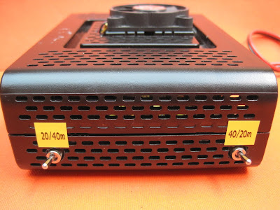
This is the side with the two switches for the LPF selection. Of course both switches must be on the correct position. I didn't want to put input and output on the same switch to avoid unwanted copupling, and maybe causiong oscillation.
And this was the end result

And here a view of the amplifier in use on a SOTA activation (2/9/2020 on ON/ON-027).
KX3 > Amplifier > Z-100 Autotuner. The setup was powered from a 12V/17Ah gel cell.
The Z-100 is to be replaced by the smaller ATU-100, another Chinese kit, which I described here:
Building the ATU-100

Measurements
I was also curious if the harmonics were within spec, so I used a Siglent spectrum analyser and 45 dB of attenuators in line, and at 2W input to the amplifier, I got the following results (click on the graphs to view details):
40m, mode CW, 7.033 MHz, Pout = 45W

Not a harmonic in sight, but if there are any, how big are they ?
This analyzer has a "harmonics test" mode, which instantly shows the level of all harmonics, related to the carrier power. All harmonics are more than 56 dB below carrier, so it looks very good.


Is this "linear" really linear?
I did not make any real measurements (yet), but just tried the amplifier on the air in SSB mode during my SOTA activation. I asked several people who gave me a 59 report, if they heard anything special, any distortion or such ... and none of them could hear anything bad ... so far, so good.
I suppose it doesn't behave like an expensive "professional" amplifier, but we"re only "amateurs" after all ...
If I ever get to make real measurements of the linearity, I'll update my post.
And now for real ...
After I boxed the amplifier, I did some brief test transmissions (3x CQ RBN on each band), and checked RBN for the results. See for yourself ... not bad eh ?

Conclusion
I'm quite satisfied with the result of this cheap amplifier. Total cost, with the LPF ringcores I had to buy, the rest being "free" stuff from my junk box, was under 20$.
I can use it on 4 bands, with both my KX3 and my two QCX rigs, delivering some 40-ish watts of power. Nice !
If you found anything useful in this report, let me know !
73,
Luc - ON7DQ
No comments:
Post a Comment
All reactions will be moderated. Publicity or links to other sites are not allowed.