24/09/2021

Cerro La Mola

EA5/AT-040, Cerro La Mola


I tricked my girlfriend into this last summit with the promise that there is a nice "Gaudi style" church on the summit ... well, kind of ...
This church and the ruins of a castle are next to the parking lot at position 38.409362, -0.794555
The church is called"Santuario de Santa María Magdalena" and the castle is  "Castillo de la Mola", see these websites for more info:
and


Now the SOTA summit is still more than an hour from the parking lot, it's a 1.2 km walk, with 185m ascent. This is the track we followed, it's the same as on the SMP by Thomas, DL8DBW.
The same advice as always ... if you do this walk on a hot day like we did, take enough water !


At first you pass an abandoned quarry, then have to find the start of the path, but it is very well indicated with white and orange stripes. The first part is a bit steep, later it gets flatter, and then the final climb is again a bit steeper. A walking stick is a good help at some points.

The quarry.


Start of the track.


Final climb to the summit, but beware, the top in the middle of the picture is not the summit ... yet!
The summit is still another climb over the rigde to the right.


No radio towers at the summit, lots of space for antennas, and a n ice view of the church and castle, as you can see in the short video below the picture.


Luckily I brought my umbrella and wore a hat, so I could operate in the shade ;-)


This concludes the short EA5 trip of 2021. See you all on another one ...

73, Luc - ON7DQ

23/09/2021

Llorensa

EA5/AT-037, Llorensa

After a visit to Benidorm and Calpe, I had planned this easy drive-up summit. We approched it from the south, through a labyrinth of streets going through holiday homes of the "Urbanización Cumbre del Sol". As we got nearer, we entered a dense fog which also covered the summit. So far for the nice views ... and not much "sol" in the air !  Parking position was 38.719929, 0.159624


I quickly set up beside the road, and started my activation. It was not really cold, but there was a lot of wind and the air was very humid, so not a very pleasant stay.


Despite the circumstances, I was still happy with 25 QSO's in the log, and working ZL1TM as best DX made my day !


Here a few videos to give you an idea of the operating conditions ...


>>> Continue to the NEXT summit.


19/09/2021

Cocón de Cope

EA5/MU-162 Cocón de Cope

In 2020, I planned a nice three week trip to the Murcia - Valencia area with my new YL, but we had to cancel it due to Covid-19. This year, after we were both fully vaccinated, we decided to do a short version of this trip, limiting ourselves to the area between Murcia and Alicante. 
Finding some nice places to stay was a bit difficult, and in the end we ended up in three different spots (1-2-3 on the map below):
1. Aguilas on the 'Costa Calida' (the warm coast), 
2. Aiguës near Alicante, and finally 
3. Torre-Pacheco, which was very convenient because it is close to the Murcia-Corvera airport.

(click on the pictures to have a better view)


With only 12 days available (actually 10 days if you don't take into account the flights), I had to limit the SOTA activations to only three summits. But that was enough to get the EA5 Association on my list for the Mountain Explorer Award, and I even got a first activation of a summit. Nice !

ꙮꙮꙮꙮꙮ


The first summit was EA5/MU-162 Cocón de Cope. It is near Cabo de Cope and its' lookout tower, Torre de Cope. The nearest village is Calabardina. Parking position is 37.436556, -1.484821


The area is also known for its fossile dunes, very nice to have a short visit.


This is the track we walked, you can also find it in GPX format on the Sota Mapping site, or download it via SOTLAS. Note that this summit also has a trig point (vertice) which is valid for the Spanish DVGE program, but this  point is NOT in the activation zone for SOTA. 


Like most tracks, the beginning looks easy ...


Only after about two thirds along the way to the top, it began to get steeper and steeper. 


And the final part to the summit is just finding your own way, scrambling over the rocks ...
To my surprise, I saw that somebody was already on the summit. But when we approached, they were already descending, and getting closer, I could see the young girl of the couple was wearing nothing but a string bikini, and trainer shoes ... proper mountain attire , HI !


Finally reaching the summit, I could see that it had a lot of space for antennas, so I decided to put up my "long endfed".  Now, normally I carry two pieces of random wire in my backpack, one is 9.15m long, the other is 22m. To reduce the combined weight, I did some rethinking, and made an extension to the 9.15m wire (22 - 9.15 = 12.85m), so I had less wire to carry. The end result is the same.


Proof that my new system worked is the number of QSO's : 58 in total, including some DX, and 5 S2S contacts. This was also a FIRST activation for SOTA.
I was especially pleased to work friends Gary W0MNA and Martha W0ERI from the state of Kansas, USA !


Here a view from the summit to the West, showing the DVGE vertice (VGMU-018) on the lower summit, and the bay of Calabardina in the background.


>>> Continue to the NEXT summit.


30/08/2021

The Clothespeg Paddle V2.0

ON7DQ Clothespeg Paddle V2.0


In April 2017 I built my first "clothespeg" paddle. It was more of a joke, as a reaction to this thread on the SOTA Reflector.

https://reflector.sota.org.uk/t/homebrew-mini-cw-paddles-and-video/15044/

The idea for the use of wooden dowels came from Ignacio, EA3BD, and the idea for the clothespeg actually came from John, G4YTJ.

To my surprise, the paddle worked quite well, and I used it for some SOTA activations in EA6. Later on, I also used the paddle with all of my QCX rigs, during the different QCX QSO Parties.


But when working no one else than EA2BD who was doing a SOTA activation (and I was operating from the beach with my QCX Mini), I began to get erratic keying, and after investigating, it seemed that the self-adhesive copper foil I used was being pulled loose by the wires. Because I soldered the wires a bit too close to the center pillar, it began making contact even when I did not touch the paddle.

There was another flaw in my first paddle, the wooden dowels holding the pegs were mounted perfectly vertical, but that way  the paddle would slowly work itself upward and become loose, so I had to make a "top cover".

So it was time for V2.0 !

The following pictures will give you a good idea of how to make one for yourself, it's not complicated at all.

Making the base


I took a piece of wood approx. 57 by 34 mm, and 10 mm thick. See some dimensions in the drawing below. You may have to change some measurements, because well ... not all clothespegs were created equal, hi.


On the front to back centerline, drill two holes, the size of some wooden dowels. I used a 6 mm drill, which made the dowels press-fit.

You'll need three dowels of about 25 mm long. I used a chopstick to make the dowels.
In my first paddle, I used also a wooden dowel for the ground contact, clad with copper foil. But this time I use a hexagonal standoff (from the junkbox), which allso presses into a 6 mm hole, and used an eyelet and a screw.

The two "side dowels" are slightly tilted inward, by putting a small piece of cardboard under the opposite side when drilling the holes.

To measure where to drill the holes for the two side dowels, I put two pieces of cardboard, 1 mm thick between the paddles, so my contact spacing would be about 1 mm, which is fairly wide. You can adjust that spacing later, see below.

Two pieces of self-adhesive copper tape were put in the appropriate places. Again, this may differ from model to model.
If you have no such copper foil, you may glue two thin copper or tinned plates to the paddles, like the screening plates of a TV tuner, cut some metal from a Coke can, etc. Use your imagination.

Clothespeg becomes two paddles


I also found a rather sloppy spring in my junkbox, probably from the battery compartment of a toy.
One end was bent over and pressed in a 0.8 mm hole in the left paddle. I drilled another 0.8 mm hole in the other paddle, just for the picture, to show the position of the hole.

Then came the connecting cable. I cut a 3.5 mm stereo cable in two. I drilled a 3.5 mm hole right behind the center post. Then with some luck, and careful aiming ... I could drill another 3.5 mm hole from the back, horizontally through the base, and it ended in that first hole. Some fiddling with fine tweezers ...and I pulled the three wires of the cable through the hole.
The ground contact is soldered to the eyelet on the center post. The other wires are soldered to the copper foil, in the small indent in the paddles, where I also pushed some foil into.

Cable and spring inserted, ready for assembly !


The whole assembly with the spring slides just between the two middle dowels, and needs no other fixing. The weak point will probably be the flexing wires to the paddles, but that is easily repaired.

If you think the spacing is too wide for you, it can be adjusted by slipping a piece of shrink tubing, or the rubber piece of a mini crocodile clip, etc .. over the back pillar. See two examples below.
You could even make an oval shaped back pillar that you turn around to have a continously adjustable spacing, but I wanted to keep things simple!


Adjusting the contact spacing


Here you see the paddle in action during it's first test this afternoon, during the QCX Challenge.
I made 4 QSO's with it, and made very few errors.   


When all is to my liking, I may fill the holes of the center post and the hole for the cable with some two-component epoxy.

Have fun !

73,

Luc ON7DQ

16/08/2021

OST Morse Box DG - ON7DQ Version


The OST Morse Box project started in april 2020, see my original post about it here

Since then, a lot has happened. 
I wrote several articles about it, they were published in various printed and online magazines, in Dutch, French, German and English. Soon there will be a Spanish article too.

The basic instruction manual is available in Dutch, English and Spanish.

All info on the basic version can be found on github.

Meanwhile, Gil ONL12523 kept on programming ... and the result was an expanded version, called the OST Morse Box DG. It included a decoder and a basic sine wave generator for test purposes, and for adjusting the decoder. The built-in keyer was expanded with iambic A and B modes.

Info for this expanded version is on another github page here.

I built the first prototype on a single sided PCB, where Gil had made the "top plane" with wires ... and it worked (of course !). In a hurry I built it into a plastic cigar box.
Not really a very attractive thing ...


Recently I was looking for a new project, and thought, why not rebuild the Morse Box, but now with all the possible bells & whistles, so as to have a nice looking "presentation model".

So this is the result of my work, see top picture.
My box has the basic PCB (left side of the front panel), and the two different decoders with controls (right side of the panel). 

Added features are : switches for Power, PTT disable, decoder selection (PLL or BPF), selection of input signal : internal (from the VHF/UHF transceiver) or external (e.g. from an HF transeiver).
An LED as a tuning aid for decoding signals with the PLL decoder.

Internally I added two small slide switches, one to disable the power bank "keep alive" feature, which generates a ticking noise. And one to short out resistor R7, to increase the MIC level for Yaesu transceivers. 

Two pushbuttons were also added, one for switching the decoder ON or OFF, and a RESET button on the back panel. As I was looking at the decoder ON/OFF button, I thought it would be nice if I could also start the generator with that button, so I asked Gil if that would be possible?

Of course it was, so there is now a version 2.12 of the Arduino firmware, where the decoder button works as follows (supposing the decoder was ON) :
> Decoder OFF > Generator ON > Generator OFF and Decoder back ON.
Those that don't want any decoders, can touch the key or paddle to switch OFF the generator, this will also leave the decoder in the OFF state.

Here follow some more details. Click on the pictures to see them in a better resolution.

I started by cutting a few pieces of single sided PCB. The dimensions of the box were inspired by the size of the front panel of an IC-9700, so that the box can be put nicely on top of it : it's 9 by 23 by 9 cm (H/W/D)


I soldered the back panel to the bottom panel, and added two side strips, where I could fix the cover using small Parker screws.

The front panel was soldered after most of the insides were mounted.

Drilling and filing all the holes was a lot of work, especially measuring the correct position !

But after a while , it started looking like this. There are 19 holes in the front, and 10 in the back !


The front panel was again removed and all sides were spray painted with two layers of a light gray matte finish.

Then all the labels were put on, just using Scotch tape, nothing fancy.

I tried using a clear spray varnish on a test panel, where I fixed some labels with Pritt glue, Velpon glue or Scotch tape.
I was not a big success, rather one big failure ...
The chemicals in the varnish (aceton ?) did no good to the toner from the printer, and where I used Scotch tape it affected the edges of the tape.


Two points which you may find interesting, is how I mounted the decoders and the OLED display.

The two decoder boards were mounted just hanging from their potentiometers. I made a kind of "brigde" with three holes for the potentiometers. The bridge is then soldered to the front panel, so you don't see any nuts on the front panel, and I had only to drill three small holes for the 4mm shafts.


Same principle for the OLED display. Two supports left and right of the display support a "bridge", which has adjustable slots, so that I can put some pressure on it. A piece of soft rubber insulation (from a test lead) makes sure I don't crack the display board, or short any components it may touch.


On the picture above you can also see the two small slide switches (near the top right), an internal speaker (bottom left) and the RESET pushbutton (bottom right).


Here is a close view of the front panel. 


The two switches for RANDOM and BEACON are of the special ON-OFF-(ON) type as suggested in the basic manual. This means they function as a pushbutton when pushed down (non locking), and as a switch (locking) when pushed upward.

It also contains a built-in Touch Paddle (bottom right).
The paddle was made after the description in the basic manual. The ground strips were soldered to the bottom plate of the case.

And this is the back panel.


Most of the connections are on the PCB of the basic version. The extra stuff is : EXT IN, to connect signal from an external receiver to the decoders. A DC 12V power input, feeding the 7808 voltage regulator on the PCB. The RESET button. 

Finally, a cover was made from an old cover from a server. It was cut and bent into shape, and spray painted with two layers of red paint. 

ꙮꙮꙮꙮ

While rebuilding the OST Morse Box, I also did a few small changes.

When using headphones, one may notice the computer noise from the Arduino and/or connected PC.
Adding a 47µF/10V electrolytic capacitor between pins 7 and pin 4 (GND) on the LM386 solves this problem (any value between 10µF ... 100µF will do).


Adding a switch to disconnect R12 from 5V, to disable the keep alive circuit.

Adding a switch to short out R7 to increase the modulation level for Yaesu transceivers.

Replacing the fuse I put in earlier, by an LM7808 voltage regulator. A heatsink was not necessary, but I put one anyway.

At the jumper block, I added test points (stiff wires) to connect GND, +5V, and Signal IN for the decoders. I could solder to these points even after the PCB was mounted in the case.

The 12V DC input is connected to pin 17 on the jumper block, named +9V in the manual.

Pin 19 on the jumper block, the PTT signal,  is routed over a switch on the front panel, and then to the transceiver PTT line. This is handy if you want to do some code practice without transmitting, but still want to be standby on the local channel for a voice QSO.  PTT from the microphone will remain functional.


Finally the decoder switching was done according to this diagram.


The SIGNAL switch selects between the audio from the VHF/UHF transceiver or an external source, and feeds both decoders at the same time. Both decoders are also supplied with +5V all the time

The second switch selects which decoder will be used.
Only one of the decoders' output is connected to Arduino input D2 (on the paddle test jumper).
The LED output is also switched.


It may all seem a rats nest in the end, but when the lid is on, it looks really nice ... what do you think ?

73,

Luc ON7DQ

24/02/2021

Sunniest Winter Bonus Points Ever


Predictions for Wednesday Feb 24th were excellent, sunshine all day and temperatures up to 18 °C, so I had to grab this opportunity.

Leaving my home QTH at the unholy hour of 05:25, I arrived almost three hours later on the first summit, ON/ON-001. I took my breakfast on a parking spot along the road.


ON/ON-001, Signal de Botrange - 695m, 8 points

Setting up on the parking lot (position 50.501208, 6.093355) was not easy, no way you can get any pin in the ground there, it’s all rocks.So I used part of a fallen tree to support my fishing pole, and installed my “long endfed”, 23m of wire with a 9:1 UNUN.


Last time I was on this summit (in Dec 2020), that UNUN showed a bad contact, making me call CQ on a piece of coax only 3.5m long … still Lars, @SA4BLM picked up my signal at 339, amazing.

I had checked the UNUN at home and couldn’t find anything wrong with it. But again, it behaved badly, it seems the BNC connector got loose and started turning a little, but by fiddling a little I could get it working, and had no more problem on the other summits.

To please the ON stations, I started on 80m CW. But who was the first caller? SA4BLM, him again, hi. I think Lars sleeps at his transceiver (or maybe his transceiver is next to his bed ?).

After logging 9 stations in CW and 10 in SSB, I moved to 40m, resulting in a small pile up, 32 more QSO’s in the log, including 2 S2S. A nice result, 51 QSO’s in 50 minutes, I can live with that.

Since it is now forbidden to leave Belgium, I had a walking track from the Belgian side to the summit ON/ON-009 (Iverst) from Peter, ON4UP. He had done this walk on the Monday before, but I decided that I would lose too much time and skipped this one.


ON/ON-011, Sur Clair Fa - 601m, 8 points


From my parking spot at position 50.319998, 5.972385, I walked 5 minutes to the East, to my operating spot at 50.320594, 5.976140, which is just in the AZ.

Again using the long endfed, I started on 80m and got 9 callers. In between, I catched a few S2S on 40m. That is the main reason I use this non-resonant endfed, change band, press autotune and GO.


After that I went to 60m SSB (8 Q’s), 40m SSB (7 Q’s) and ended with 30m CW (2 Q’s). I had to stop then, because I was already one hour behind on my schedule.

BUT, I gained some time by trying out a new parking spot for my next summit, ON/ON-013.


ON/ON-013, Bois de Hodinfosse - 568m, 6 points


I have activated this summit 4 times before, using the parking spot indicated by G4OBK, and then walking a steep slope for 30 minutes.


I had seen on the maps that in the village of Arbrefontaine, one can drive the road called “Le Calvaire” to a much higher altitude than I used to do. Now take care, because almost all roads are called “Le Calvaire” over there, hi … see map below (source: Google Maps).

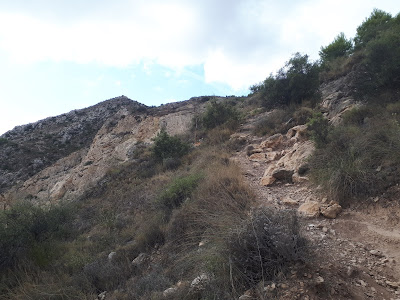
If you see this view to your right , you know you have the “right” one, although technically it is the “left” road on the map, hi.


The white structures are the stations of a Calvary or "Way of the Cross". More info about them is here (in French): 

At the start of the road, there's a sign saying it is a dead end street, but you can drive this road to this parking spot 50.316070, 5.841752, turn your car and park at the downward side.

From there it is less than 500m walking to this operating position 50.314296, 5.848018.
It is a much easier walk, with only 25m ascent, and the operating spot is at 560m, so well into the AZ.
From there, you also have a nice view over the area below since it is an open field.


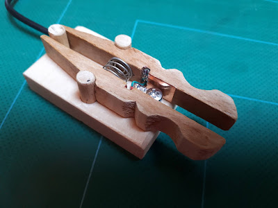
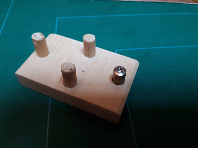
On this summit, I wanted to try my new QCX Mini, a 17m model. 
See my posts about this little marvel here and here and here.

Power was from a 3-cell battery box, the antenna a half-wave “Fuchs” antenna (length 8.9m), sloping from abt. 6m above ground to 0.5m (tied to the arm of my chair … ensuring “armchair” copy, hi).
A 4m counterpoise completed the setup.


The Fuchs tuner plugs directly on the QCX Mini, so no feedline losses. I didn’t have any RF feedback problems like others reported, but I did notice a “raspy” sidetone that I don’t have using the rig at home on an external antenna. An advantage of this is that the raspier the tone, the better my Fuchs tuner is tuned, no need to look at the LED.

First I called on 18.092 , but despite being spotted on SOTAwatch, I got only one reply, from UR5IRM, who gave me a 559. More calling … NIL replies. The band was probably not at its best, so it was time for plan B.

Adding 2.2m of wire to the antenna, and retuning my Fuchs tuner, I started CQ’ing on 14.062, with reduced power of 4W, and reduced RX sensitivity of about 1 S-point.

I almost fell off my chair when the first reply was from no one else than … ZL1TM, Andrei in Auckland, New Zealand ! 
He was a good 539 with me, and he gave me a 509.
That was the first ever ZL in my SOTA activator log. WOW.

Further QSO’s with OH5RP, EA5K, EA7GV, OH6JUM, EA7TG, SV2OXS and YL2TQ proved that “abusing” a QCX on the “one lower” band is certainly feasible.

To please the non-CW chasers, I switched to the KX3 + my short endfed (9.15m) to calll a bit more on 40m SSB, and ended the activation with 21 QSO’s in the log, including 2 S2S.


ON/ON-010, Baraque Fraiture - 651m, 8 points

Last summit of the day was another “parking lot” operation at ON/ON-010, parking position is 50.253133, 5.731574 .

Had there been snow, that lot would have been full, but now it was as empty as can be, and parking was free. The temperature was a nice 18.5 °C.

I set up my short endfed again, and filled my log with another 26 QSO’s on 20/30/40/60m, mixing SSB and CW. And then it was time to take the long drive home.


Some statistics:

I drove my car for a total of 6 hours and 50 minutes, and I was out in the open for 7 hours and 5 minutes, of which I played radio for 3 hours and 50 minutes.

Total driving distance 588 km, using up almost a full tank of gas, costing about 55€.

Activator points +42 (now at 1299), S2S points +64 (now at 3333), and Chaser points +52 (now at 15269)


And that concludes my report of a most enjoyable SOTA day trip

73,

Luc ON7DQ