30/08/2021

The Clothespeg Paddle V2.0

ON7DQ Clothespeg Paddle V2.0


In April 2017 I built my first "clothespeg" paddle. It was more of a joke, as a reaction to this thread on the SOTA Reflector.

https://reflector.sota.org.uk/t/homebrew-mini-cw-paddles-and-video/15044/

The idea for the use of wooden dowels came from Ignacio, EA3BD, and the idea for the clothespeg actually came from John, G4YTJ.

To my surprise, the paddle worked quite well, and I used it for some SOTA activations in EA6. Later on, I also used the paddle with all of my QCX rigs, during the different QCX QSO Parties.


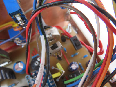
But when working no one else than EA2BD who was doing a SOTA activation (and I was operating from the beach with my QCX Mini), I began to get erratic keying, and after investigating, it seemed that the self-adhesive copper foil I used was being pulled loose by the wires. Because I soldered the wires a bit too close to the center pillar, it began making contact even when I did not touch the paddle.

There was another flaw in my first paddle, the wooden dowels holding the pegs were mounted perfectly vertical, but that way  the paddle would slowly work itself upward and become loose, so I had to make a "top cover".

So it was time for V2.0 !

The following pictures will give you a good idea of how to make one for yourself, it's not complicated at all.

Making the base


I took a piece of wood approx. 57 by 34 mm, and 10 mm thick. See some dimensions in the drawing below. You may have to change some measurements, because well ... not all clothespegs were created equal, hi.


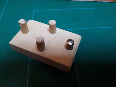
On the front to back centerline, drill two holes, the size of some wooden dowels. I used a 6 mm drill, which made the dowels press-fit.

You'll need three dowels of about 25 mm long. I used a chopstick to make the dowels.
In my first paddle, I used also a wooden dowel for the ground contact, clad with copper foil. But this time I use a hexagonal standoff (from the junkbox), which allso presses into a 6 mm hole, and used an eyelet and a screw.

The two "side dowels" are slightly tilted inward, by putting a small piece of cardboard under the opposite side when drilling the holes.

To measure where to drill the holes for the two side dowels, I put two pieces of cardboard, 1 mm thick between the paddles, so my contact spacing would be about 1 mm, which is fairly wide. You can adjust that spacing later, see below.

Two pieces of self-adhesive copper tape were put in the appropriate places. Again, this may differ from model to model.
If you have no such copper foil, you may glue two thin copper or tinned plates to the paddles, like the screening plates of a TV tuner, cut some metal from a Coke can, etc. Use your imagination.

Clothespeg becomes two paddles


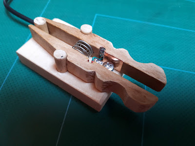
I also found a rather sloppy spring in my junkbox, probably from the battery compartment of a toy.
One end was bent over and pressed in a 0.8 mm hole in the left paddle. I drilled another 0.8 mm hole in the other paddle, just for the picture, to show the position of the hole.

Then came the connecting cable. I cut a 3.5 mm stereo cable in two. I drilled a 3.5 mm hole right behind the center post. Then with some luck, and careful aiming ... I could drill another 3.5 mm hole from the back, horizontally through the base, and it ended in that first hole. Some fiddling with fine tweezers ...and I pulled the three wires of the cable through the hole.
The ground contact is soldered to the eyelet on the center post. The other wires are soldered to the copper foil, in the small indent in the paddles, where I also pushed some foil into.

Cable and spring inserted, ready for assembly !


The whole assembly with the spring slides just between the two middle dowels, and needs no other fixing. The weak point will probably be the flexing wires to the paddles, but that is easily repaired.

If you think the spacing is too wide for you, it can be adjusted by slipping a piece of shrink tubing, or the rubber piece of a mini crocodile clip, etc .. over the back pillar. See two examples below.
You could even make an oval shaped back pillar that you turn around to have a continously adjustable spacing, but I wanted to keep things simple!


Adjusting the contact spacing


Here you see the paddle in action during it's first test this afternoon, during the QCX Challenge.
I made 4 QSO's with it, and made very few errors.   


When all is to my liking, I may fill the holes of the center post and the hole for the cable with some two-component epoxy.

Have fun !

73,

Luc ON7DQ

16/08/2021

OST Morse Box DG - ON7DQ Version


The OST Morse Box project started in april 2020, see my original post about it here

Since then, a lot has happened. 
I wrote several articles about it, they were published in various printed and online magazines, in Dutch, French, German and English. Soon there will be a Spanish article too.

The basic instruction manual is available in Dutch, English and Spanish.

All info on the basic version can be found on github.

Meanwhile, Gil ONL12523 kept on programming ... and the result was an expanded version, called the OST Morse Box DG. It included a decoder and a basic sine wave generator for test purposes, and for adjusting the decoder. The built-in keyer was expanded with iambic A and B modes.

Info for this expanded version is on another github page here.

I built the first prototype on a single sided PCB, where Gil had made the "top plane" with wires ... and it worked (of course !). In a hurry I built it into a plastic cigar box.
Not really a very attractive thing ...


Recently I was looking for a new project, and thought, why not rebuild the Morse Box, but now with all the possible bells & whistles, so as to have a nice looking "presentation model".

So this is the result of my work, see top picture.
My box has the basic PCB (left side of the front panel), and the two different decoders with controls (right side of the panel). 

Added features are : switches for Power, PTT disable, decoder selection (PLL or BPF), selection of input signal : internal (from the VHF/UHF transceiver) or external (e.g. from an HF transeiver).
An LED as a tuning aid for decoding signals with the PLL decoder.

Internally I added two small slide switches, one to disable the power bank "keep alive" feature, which generates a ticking noise. And one to short out resistor R7, to increase the MIC level for Yaesu transceivers. 

Two pushbuttons were also added, one for switching the decoder ON or OFF, and a RESET button on the back panel. As I was looking at the decoder ON/OFF button, I thought it would be nice if I could also start the generator with that button, so I asked Gil if that would be possible?

Of course it was, so there is now a version 2.12 of the Arduino firmware, where the decoder button works as follows (supposing the decoder was ON) :
> Decoder OFF > Generator ON > Generator OFF and Decoder back ON.
Those that don't want any decoders, can touch the key or paddle to switch OFF the generator, this will also leave the decoder in the OFF state.

Here follow some more details. Click on the pictures to see them in a better resolution.

I started by cutting a few pieces of single sided PCB. The dimensions of the box were inspired by the size of the front panel of an IC-9700, so that the box can be put nicely on top of it : it's 9 by 23 by 9 cm (H/W/D)


I soldered the back panel to the bottom panel, and added two side strips, where I could fix the cover using small Parker screws.

The front panel was soldered after most of the insides were mounted.

Drilling and filing all the holes was a lot of work, especially measuring the correct position !

But after a while , it started looking like this. There are 19 holes in the front, and 10 in the back !


The front panel was again removed and all sides were spray painted with two layers of a light gray matte finish.

Then all the labels were put on, just using Scotch tape, nothing fancy.

I tried using a clear spray varnish on a test panel, where I fixed some labels with Pritt glue, Velpon glue or Scotch tape.
I was not a big success, rather one big failure ...
The chemicals in the varnish (aceton ?) did no good to the toner from the printer, and where I used Scotch tape it affected the edges of the tape.


Two points which you may find interesting, is how I mounted the decoders and the OLED display.

The two decoder boards were mounted just hanging from their potentiometers. I made a kind of "brigde" with three holes for the potentiometers. The bridge is then soldered to the front panel, so you don't see any nuts on the front panel, and I had only to drill three small holes for the 4mm shafts.


Same principle for the OLED display. Two supports left and right of the display support a "bridge", which has adjustable slots, so that I can put some pressure on it. A piece of soft rubber insulation (from a test lead) makes sure I don't crack the display board, or short any components it may touch.


On the picture above you can also see the two small slide switches (near the top right), an internal speaker (bottom left) and the RESET pushbutton (bottom right).


Here is a close view of the front panel. 


The two switches for RANDOM and BEACON are of the special ON-OFF-(ON) type as suggested in the basic manual. This means they function as a pushbutton when pushed down (non locking), and as a switch (locking) when pushed upward.

It also contains a built-in Touch Paddle (bottom right).
The paddle was made after the description in the basic manual. The ground strips were soldered to the bottom plate of the case.

And this is the back panel.


Most of the connections are on the PCB of the basic version. The extra stuff is : EXT IN, to connect signal from an external receiver to the decoders. A DC 12V power input, feeding the 7808 voltage regulator on the PCB. The RESET button. 

Finally, a cover was made from an old cover from a server. It was cut and bent into shape, and spray painted with two layers of red paint. 

ꙮꙮꙮꙮ

While rebuilding the OST Morse Box, I also did a few small changes.

When using headphones, one may notice the computer noise from the Arduino and/or connected PC.
Adding a 47µF/10V electrolytic capacitor between pins 7 and pin 4 (GND) on the LM386 solves this problem (any value between 10µF ... 100µF will do).


Adding a switch to disconnect R12 from 5V, to disable the keep alive circuit.

Adding a switch to short out R7 to increase the modulation level for Yaesu transceivers.

Replacing the fuse I put in earlier, by an LM7808 voltage regulator. A heatsink was not necessary, but I put one anyway.

At the jumper block, I added test points (stiff wires) to connect GND, +5V, and Signal IN for the decoders. I could solder to these points even after the PCB was mounted in the case.

The 12V DC input is connected to pin 17 on the jumper block, named +9V in the manual.

Pin 19 on the jumper block, the PTT signal,  is routed over a switch on the front panel, and then to the transceiver PTT line. This is handy if you want to do some code practice without transmitting, but still want to be standby on the local channel for a voice QSO.  PTT from the microphone will remain functional.


Finally the decoder switching was done according to this diagram.


The SIGNAL switch selects between the audio from the VHF/UHF transceiver or an external source, and feeds both decoders at the same time. Both decoders are also supplied with +5V all the time

The second switch selects which decoder will be used.
Only one of the decoders' output is connected to Arduino input D2 (on the paddle test jumper).
The LED output is also switched.


It may all seem a rats nest in the end, but when the lid is on, it looks really nice ... what do you think ?

73,

Luc ON7DQ