OK, Hans thinks I have a FUSE fetish, but I'm also obsessed with using the QCX (Mini) on the "one lower" band without too much trouble. If I can get something for FREE ...
I don't want to modify the QCX inside (except for that FUSE! haha), partly scared to brick it , but also to keep it in its' "mint in box" condition.
One possible problem was the 2nd harmonic suppression when I use the 17m Mini on 20m (see my measurments page here ). I don't think it is a real problem if your QRP rig has a second harmonic 39 or 43 dB below the carrier, the potential interference will be very low anyway.
But ok, I had to investigate if something could be done about it, so I did a few experiments.
Of course, everything had to be as cheap and simple as possible.
First experiment : an outboard LPF for 20m
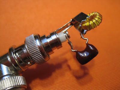
I happened to have two suitable BNC connectors, one a male PCB mount connector (found those in China), and a right angle female BNC (junkbox).
The filter is a simple 3-element LPF, existing of 2 x 180 pF capacitors, and 15 turns on a T37-6 (meaured L was 675 nH). I used wire from the QCX Mini kit, I still have plenty, since the supplied wire should be sufficient to wind a T1 for 80m.
I first prepared a small piece of PCB with a Dremel tool, and drilled all the holes.
Then mounted the components and connectors.
TIP: to solder those connectors, you need a fair amount of heat. Put a matching BNC in them while soldering, especially those Chinese connectors don't contain a Teflon, but a simple white plastic insulator. How I know ? Well, you know ... hi.

This is the filter response. Nothing spectacular, but the extra 11 dB suppression should do the trick.
An extra loss of 0.34 dB on 20 m was not so welcome, I had only 4 W on 20 m to start with ...
Still, let's try the LPF in combination with the QCX Mini ...
See picture at the top, the filter is very small, and fits nicely on the side of the QCX Mini.
I didn't put it in a box, but I could wrap it up in rubber tape if needed.
This is what comes out of this setup.
The power drops to
3.22 W, I guess that is still enough to make a QSO, and it's plenty of power if you want to do some WSPR or QRSS.
The good news is that all harmonics are now more than 58 dB below the carrier!
To know that you obey all the rules is such a good feeling isn't it? 😁
Now, will I use this filter for real ?
Hmm, probably not!
If I leave the filter plugged in by accident, and I start transmitting on 17m, I will get a high SWR and low output power, possibly ruining the QCX, and not making many QSO's.
So let's try something else ...
Second experiment: harmonic suppression with a series L/C circuit.
What if we could remove the 20m harmonic by shunting it with a short circuit, and leave all the rest untouched ?
That's what a series L/C network does, if tuned to 28 MHz, and put in parallel on the QCX output.
OK, let's make one.
Another T37-6 ringcore, winding it with 13 turns (YES, still with wire from the QCX Mini kit!), measured inductance abt. 500 nH.
A 47 pF capacitor in series, and all was mounted on a cheap, solder type BNC connector.
Using the nanoVNA for a quick check showed that I could easily tune the L/C to 28.1 MHz by shiftng a few turns on the ringcore (note that the nanoVNA was not calibrated, it shows 10 dB loss in the passband).
[NOTE: on the SOTA Reflector Pascal, VK2IHL showed how it should really be done, with a "2nd Order Legendre Bandstop Filter, mainaining 50 Ohm all the time ... read that post
here Now that is a mouthful, and also defies my principle of cheap and simple ... hi]
This circuit will of course also have some effect on the signals at 14 and 18 MHz, but how much?
One way to find out is to try it.
And what I got was a big surprise!
Here the measurement, transmitting at 14.060 MHz.
At Vcc = 12 V, I got MORE power out, it went from 4 W to 5 W, WOW!
And the harmonic was -62 dBc, so very good.
But what at 18 MHz ?
There, the power dropped from 6 W to only 5 W.
The harmonic suppression remained at -57 dBc.
Of course it’s not all glitter and gold … there is another problem popping up now:
SWR gets worse by adding the circuit.
Putting the QCX on a dummyload, I got an SWR = 1 of course (*).
Adding the circuit on the BNC T-piece gave a higher SWR of 1.2 on 14 MHz and 1.45 on 18 MHz.
Not dramatic, but also not very good.
One advantage: it won’t hurt (too) much if you let the circuit in place for 18 MHz, but of course it would be better to remove it, both Power- and SWR-wise.
And it is surely better than letting my 14 MHz LPF in place and start transmitting on 17m.
Conclusion
In my opinion, the second solution is cheap, simple and the most desirable one, to make your QCX (+/Mini) into a dual-bander, with reasonable output power, harmonics within spec, and a slightly lower RX sensitivity on the "one lower" band (see previeous post on Measurements
here).
I hope you found my musings interesting, all comments welcome!
73,
Luc, ON7DQ
.


No comments:
Post a Comment
All reactions will be moderated. Publicity or links to other sites are not allowed.