12/02/2023

SOTA Winter Tour 2023


Last year I did most of this tour together with Rob, ON4ROB. Rob has decided he wants to go for 100% uniques, so I was on my own again this year. The weather looked good, cold but dry … at least that was the forecast.

So I booked a room on AirBnb for one night near Bastogne, and off I went on Saturday Feb 11th, at 05:30 local time.

The weather was not exactly as promised : quite a bit of fog the whole day, and some drizzle, mostly in the afternoon. Well, at least the roads were without snow, so still a good day to tour these “Winter Bonus” summits. Here a short overview of the tour, with some summit info.

Total distance driven: 745 km, fuel cost €91.14, AirBnb €35.

DAY 1 - Saturday, Feb 11th

05:25 Leave home

07:15 Have breakfast along the highway (193km)

08:25 (258km)
ON/ON-001, Signal de Botrange - 694m, 8 points (GPS : 50.501208, 6.093355, is in AZ)


Big surprise here: the parking lot had been asphalted, it looks very nice now, no more mud pools …

I set up near the South end of the parking lot, and hey … I even managed to get the spike for my fishing pole into the ground, that never happened before.
I used my longer random wire (22.3m) so I could start my activation on 80m.


I got 6 callers on 80m CW, and then made 24 more on 40m and 20m, both in CW and SSB.
But I got another surprise when I wanted to switch to SSB. My headset has a microphone (see it in the top picture), but there seemed to come no sound from it ...
That had happened before, and I could repair it each time , but maybe after 8 years of use on over 250 summits, it's time to look out for a new one , hi.
This headset has cost me only 5€, and so far I always was told the audio sounded better than any other microphone that I have used.

Time for plan B: get out the little Hama plug-in PC microphone that I always carry in the KX3 bag.
The headphone of the headset still worked, but I had a better one in my "backup/QCX bag", a fold-down Sony headset.


I also wanted to make at least one S2S QSO on each summit, it was earlybird Marcel, DM3FAM that saved the day here.

30 QSO’s, 1 S2S

10:15 (288km)
ON/ON-009, Iverst - 693m, 8 points (GPS: 50.408333, 6.369756, is in AZ)


Since 80m was not a good candidate any more, I put up the short random endfed (9.15m).

A light drizzle started coming up, so I had to protect the KX3 with some bubble plastic and a towel.
Mostly 40m and 20m , CW and SSB.

29 QSO’s, 11 S2S

12:25 (332km)
ON/ON-011, Sur Clair Fa - 601m, 8 points (Car GPS: 50.318907, 5.964020, there drive forest road to parking spot here 50.319000, 5.972406, then walk NE for about 250m until in AZ).


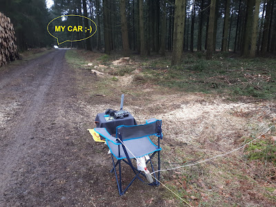
The short stretch of forest road to my parking spot was a real mudpool at the end, so I drove my car into a grassy patch, where I hoped to have some grip with the front wheels of my car. After the activation, I just put my car in reverse and let it roll backwards through the mud … until I got onto some firmer ground, then turned  the car and drove off to the next summit ;-)
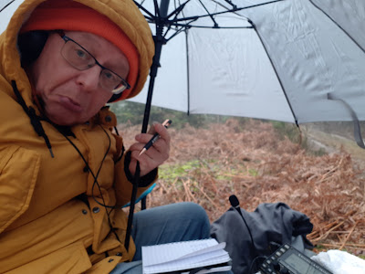
WX was still very wet and more drizzle … So I had to get out my small umbrella.
Not so pleasant, but there was virtually no wind all day, so with a temperature of about 6 °C, it was still a good activation.

30 QSO’s, 7 S2S

14:20 (348km)
ON/ON-013, Bois de Hodinfosse - 568m, 6 points (GPS: 50.316070, 5.841752, walk about 450m SE)


I had begun to like this summit, for it’s very nice view over the region, and because I had found an easier way to reach the AZ.
But this time no luck … 
I was lucky enough that I could still see my car in the foggy conditions.

My usual operating position (50.314322, 5.847850) was OK, but no views.


I set up my short antenna between the trees.


And one forgets about the miserable weather when you make some special QSO's.

After working a few S2S on 40m and 20m, I started CQ'ing on 15m CW, and WOW, I couldn't believe what I heard. After already working a few DX (4Z4DX, W4JKC), I was called by Gary W0MNA from Kansas, and a bit later by his XYL Martha, W0ERI. I had met Gary and Martha on a summit in Missouri (W0M) in April 2015. Great to have those famous chasers in my log ! 

24 QSO’s, 6 S2S


16:10 (362km)
ON/ON-010 Baraque Fraiture  - 651m, 8 points (GPS: 50.253847, 5.732054, is in AZ)


Just setting up at the end of the parking lot, no scenic views there. There was still some snow left. My big umbrella protected my gear and myself from the drizzle.

This time I tried my luck on 10m, and would you believe ... my first two callers there were again Gary and Martha. Wonderful !


Getting a bit tired after the four previous summits, I kept it short and CW only, on 17m, 20 and 40m, and then drove to my AirBnb, the first day was certainly a success.

26 QSO’s, 2 S2S

17:45 arival in my AirBnb near Bastogne (408km)

Shower, eat, sleep …

Oh, and disassemble my fishing pole, it was completely damp inside, so I put all the pieces on the heating, to dry nicely.


DAY 2 - Sunday Feb 12th

09:45 (22km)
ON/ON-004, Bois de Hazeille - 586m, 6 Points (NEW GPS position:  50.033045, 5.422340, walk 100m NW, is in AZ for SOTA and valid for POTA ON-0453)


Much better weather today, it remained dry the whole day, and I even got a glimpse of the sun at times.

I had seen that this area also has a POTA reference, ON-0453 Foret de Freyr.
But my usual operating position behind the radar tower is not valid for POTA.
So I  looked for a position where I could do a valid activation of both.
See parking position above, from there just walk North for about 100m, where you are in the POTA forest, and still in the AZ for SOTA.
So you also don't have to drive the road behind the radar station, which is in a terrible state.

I put up the long antenna again to work some 80m.


I would advise to do this one in the weekend though, when no forest work is going on. Here a panoramic view from my operating position.


Attracting chasers from both SOTA and POTA resulted in quite a pile-up, and while trying to please everyone … I got a 30 minute delay on my schedule.  But still got time to take a few nice snapshots of the environment.


45 QSO’s, 4 S2S

 12:20 (73km)

ON/ON-006, La Croix Scaille - 503m, 6 points (GPS: 49.954181, 4.844514, is in AZ)


Last year I climbed to the top of the Tour du Millenaire, but since I had already some delay, I didn’t do that this year.

I quickly set up and started my activation. It was rather calm for a Sunday, normally I see more walkers passing by, and asking some silly questions (talking to the aliens? listening to the birds ?).
None of that today ;-)

33 SO’s, 9 S2S

I had some time left to do an extra summit, no winter bonus points here, but a chance to make some more S2S QSO’s.

14:25 (115km)
ON/ON-021, Plantis de Mesnil - 306m, 2 points (GPS: 50.17735, 4.91669, walk up the forest road if you like, but even the parking spot is in the AZ).


There were again forest works going in , the whole place was a mess, so I had to park along the road.
I didn’t care to walk up to the cabin, I just  set up along the track, some 50m away from the road.

No winter bonus points on this one, but still good for some more S2S.

At 15:30 local time, I packed up, since I still had a long drive home. Traffic was not too bad, I got home without problems.

22 QSO’s, 7 S2S.

18:05 Back home in Ostend ! (336km)

See you on another SOTA adventure !

73,

Luc ON7DQ


07/02/2023

IC-7300 Paddle <> Key Switch Revisited


I have been using this mini controller for my IC-7300 almost daily since I first published it in 2017
It's still the most read post on my blog.

So far, I had only used two of the 8 buttons in the "antique" Nintendo Controller.
I'm still working on my "Big Controller" (see Part 1 ), but that project is going nowhere for the moment ...

So, recently I decided to "upgrade" my mini project, add some wires to the remaining 6 buttons, and write some more code for it. At the same time I changed the LOW POWER to 5W since I regularly do some QRP operation (NOTE : In my IC-7300 5W corresponds to 7% on the power scale).
And I added a 4-wire connection to program the Pro Mini, without opening the box.

The original circuit of those Nintendo Controllers contained a CMOS IC, type 4011.
This is an 8-bit static shift register.
But since I needed the space for my small Arduino Pro Mini, I removed that IC and used the solder pads to connect my wires to the Arduino. For those interested, I made the following connections:

Nintendo button    >>>  4011 pin number    >>> Arduino input >>> ic-7300 FUNCTION
A                    1             D9         PADDLE       [100W]
B                   15             D8         STRAIGHT KEY [5W]
START               13             D10        USB OUT = AF
SELECT              14             D11        USB OUT = IF
UP                   4             D2         SEND VOICE MEMORY 1
RIGHT                7             D3         SEND VOICE MEMORY 2
DOWN                 5             D4         SEND VOICE MEMORY 3
LEFT                 6             D5         SEND VOICE MEMORY 4

The new version of the Arduino sketch is on my github page.

Of course, it's now more than just a paddle/key switch.
You can easily modifiy the code to make the buttons do others things as well, you just have to find the correct CI-V commands to send.

At the moment, there is no way to stop the voice messages, so I may modify the code further, maybe make the AF/IF a toggle function with just one button, and use the other button as a STOP switch for the voice memories.

And you can use your own box with 8 buttons , and another Arduino model: UNO, Nano ...etc.

Good Luck !

73,
Luc ON7DQ

01/02/2023

Forty-Niner PLL

 ... another 49’er project with a digital VFO

Finished Forty Niner in a box

NOTE : this whole post talks about the popular "49'er" design by Wayne Burdick (N6KR), but  what follows is a universal PLL controller that can be applied to any direct conversion or superhet transceiver, so read on !

Introduction

This project started as a basic 49’er project, based on the QST article by Jack Purdum - W8TEE et al. "A Modular 40 Meter CW Transceiver with VFO".
That article was published in March 2016, and I read it with great interest, thinking “YES! I must build one too” … but I had never found the time to actually do it.

In autumn 2022, I finally got to order a Chinese 49’er kit, and build it with most of the changes described in the 25 page manual that can be downloaded from the ARRL here 

I asked my friend Gil (ONL12523) to write the Arduino software, like he did for the OST Morse Box.

A video on YouTube shows most of the available functions.

The Hardware

The chinese kit came without building instructions, there was only one page, containing the circuit diagram (click to enlarge). Luckily, someone posted a full manual online, click here
NOTE : DON'T BUILD the kit according to this manual, unless you only want a 1-frequency XTAL-controlled rig.

Original circuit diagram

Referring to the QST article, some more changes were needed. The AD9850 DDS has become difficult to source, and rather expensive, so it was replaced by an Si5351 module.

We also wanted to do some other stuff like keying the TX from the Arduino, generate a PTT signal to mute the receiver, or generate a variable (and perfect sinewave) sidetone in the Arduino. There is a paragraph further on with more detail of these changes ***

This is the circuit diagram with all of the modifications highlighted in yellow (click to enlarge).


I wanted our project to be “educational”, like the one in the QST article, so it had to be in a clear plastic box. At the same time I wanted it to be environmentally friendly, so it had to be some recycled box, which I found in 
the form of a case from a video cassette of the old Philips VCR standard from the seventies.

Old Philips VCR cassette (1972)

And this what I made of it. Everything is mounted on a simple L-shaped PCB chassis, which then shoves inside the box, and is fixed with double-sided adhesive tape. The 49’er board is mounted on HEX standoffs, which are soldered to the ground plane, and the perfboard with the Arduino, the voltage regulator and the Si5351 module (and an experimental CW filter) is mounted on some stiff wires that were soldered to the ground plane.

Mounting it all on a simple PCB chassis

The next picture shows the external connections, needed to operate the rig

Connectors on the 49'er PLL

And this is a view of the simple front panel before is was mounted it in the box.

The front panel

If you're in a hurry, you can skip the following paragraph.

*** More details of the hardware changes, see circuit diagram above:

-        Do not install R3, C4, C5, C6, W1 (trimmer pot), Y1 and Y2 (xtal’s)

-        Replace R5 with a 10k resistor

-        Replace C2 with 82 pF

-        Replace D2 with a 5.1V Zener diode

-        Put series LC filter (22µH + 56 pF) where Y1 was

-        Put a 3 pin header where Y2 was, connecting the middle pin to GND.

There is a nice video about building a 49’er with these changes on YouTube, click here 

Further changes we made because we used separate outputs from the SI5351 for the TX and RX oscillator, was disconnecting C10 (82pF) from pin 6 of the NE602, and feed it with the separate TX oscillator signal from CLK0. Also we made C10 1nF.

For the RX signal, the level from the Si5351 is a bit too much for the NE602, so we inserted two series capacitors (both the Si5351 and the NE602 have a DC level on their output or input), with a 220 Ω trimmer pot in between, to adjust the LO level.

D6 was disconnected from the keying line, and connected to a new NPN transistor which will serve as the PTT driven by the Arduino (I mounted it under the 49’er board with a 1k resistor at the base, and covered the resistor in shrink wrap).

In the same way, a keying transistor was put over the keying input on the 49’er, so that also the Arduino kan key the transmitter with a preprogrammed message.
An unlimited number of messages can be programmed, and those can be used as CQ or QSO messages, or as a beacon text.

The sidetone is made by the Arduino, it only needs a simple RC low pass filter.
So you can omit all components of the Twin-T oscillator, and feed the sidetone directly to pin 3 of the LM386. If you had already mounted the sidetone components on the 49’er, just remove resistor R1 to disable it.

I made a simple single stage opamp filter at 600 Hz, this is still wide enough for casual listening to SSB signals, and narrow enough to make CW operating possible.

During tests I blew up the original PA transistor (Q5, D885), and replaced it with a BD139, but mounted it in a socket made from 3 pins of an IC socket. So now I can “plug in” my final transistor like in the tube days, hi. Always handy whenever it blows again …


 Building the Arduino Controller

The Arduino circuit is nothing special, nor is it difficult, I just built it on a piece of perfboard. An Arduino Nano, a 1602 LCD display with I2C adapter (UC-146) to reduce the number of wires, and a Si5351 PLL module, also connected on the I2C bus.
A voltage regulator, and a handful of discrete components complete the circuit.
See title picture for the final result.
 

Arduino controller circuit

The software

So far so good, but then came the big disappointment … the Arduino code in the zip file from the ARRL website was far from complete: it didn’t support the RIT function like was promised in the article. The only thing it did was check the band limits for different license classes (not really needed for us in Europe), and store the last used frequency in EEPROM.

Even an updated version of the software I found in this newsgroup  was not what I was looking for. There is another solution by K4KRW, but I found it rather complicated.

So I called in the help from my good friend Gil, ONL12523, who has also written all excellent software for the OST Morse Box.

By using two of the three oscillators in the SI5351 PLL module, we were able to find an elegant solution to above problems.

Our software is now working very well, and has the following functions:
Basic operation with RIT, SPLIT and SPOT function for tuning “zero beat”.
Menu operation to select band, set lower and upper band limits, adjust OFFSET, PTT delay, WPM for the built-in messages and even a beacon function with a countdown timer.

The operation manual describes how to use the rig as a basic Code Practice Oscillator, as a beacon, or as a foxhunt transmitter.

The code also includes a software DDS generator for making a pure sinewave sidetone, the sidetone follows the chosen offset frequency and sounds just perfect.

There is even a built-in calibration routine for the Si5351 PLL module !

All needed files, with hardware and operating manuals can be found on my github page, click here 


Superhet system

Note that this concept can easily be adapted to a superheterodyne receiver, edit the code of the main sketch, and put the IF frequency in line 38:

#define IF 0000000  // enter IF frequency (in Hz) for superhet RX
                    // 0 Hz for direct conversion RX 

As an example, we used the same setup and software for an old project called BINGO (designed by Bernard, F6BCU, see some notes about the Bingo here ).
It worked first class !
This was our version of the Bingo, we built it for 80m CW.

BINGO 80m CW front panel


and the rather complicated hardware ... certainly not a backpack QRP rig !

BINGO 80m CW circuit boards


Some changes were needed in the code, because the Bingo we built used a different LCD display and a professional rotary encoder. Send me an e-mail if you need more info about that (address is good on qrz.com).

73 de Luc, ON7DQ