He had already a
very popular website (http://hanssummers.com/) which is a “homebrewers heaven” …
it contains an endless collection of nice little projects.
Later on,
Hans was very successful with a whole range of WSPR kits and addons, with his
company QRP LABS. Now WSPR is a very nice tool to check the propagation but still, you can’t make a two way qso in WSPR … so here comes the QCX !
It is a
small monoband CW transceiver which puts out between 3W - 5W (depending on
supply voltage). It was designed as a building project for the RSGB Youths On
The Air summer camp in August 2017. Since then, over 3000 of these kits have
been shipped worldwide.
I won’t
praise all it’s wonderful specs, have a look at the website for an overview.
Also , a lot
has already been written about this kit, one of the best write-ups is this one
by PD7MAA http://pa-11019.blogspot.be/2017/08/qrp-labs-qcx-5-watt-cw-trx-kit.html
And I want
to warn potential builders : this is definitely not a beginners kit !
There are
no SMD’s to solder, but the resistors and chokes are small in size and easily
damaged, and almost impossible to remove without breaking, if you make an error. Another problem area may be the 4
toroids and 1 transformer which you must wind yourself. Make sure you
thoroughly pre-tin the wires, almost half of the problems arise from bad
contacts with the toroids.
That
said, if you intend to build one … read
the FAQ and the MODS page BEFORE you start, and make note of which components
should NOT be mounted, even if the manual says so (Note : in the mean time, all
mods are gradually included in the manual, so make sure to download the latest
version).
If it all
goes wrong , there is an excellent troubleshooting guide too
But don’t
let me scare you off, if you work slowly and with good care, you can do it !
It all
starts with placing your order, for just 49$ you are in line for a cardboard
box, shipped from Japan. And the wait can be long … the kit is getting more
popular by the day …
I ordered a 20m version in October, and had to wait until end of December to
receive my kit, because the 20m LPF components were out of stock.
And then
your box arrives … this is what you get.

The two SMD
chips are pre-soldered, all other components are through hole. Everything is
very close together so just take care nothing touches where it shouldn’t touch
and you’re fine.
The 133
page manual will guide you step by step, and the drawings show exactly what
goes where. But remember to skip the components that are not needed, as
explained on the mod page. Also don’t be surprised if some trimmers have other
values … did you really read the whole MOD page ?
After a
couple of hours, your board should look like this.

Then come
the toroids !
The 4
single layer coils shouldn’t give you much trouble, but transformer T1 is the
tricky one, especially if you order a 40m or lower band kit. The manual
suggests you wind all wire at once , and make loops to cut open later and
separate the 4 different windings.

I did it a
bit differently : I wound all windings separately, scraped off the enamel and
tinned the wires. I made every wire a bit longer than the next, and so could
fit each wire in the corresponding hole , one after another with tweezers. Then
I pulled all wires one by one, until T1 sat at its final position. This is my
transformer “going in” …

Here the
kit is finished, after more or less 8 hours of work.

And of
course I had to make a qso with the board just lying on the table .. I worked
Italy after a few CQ’s , so that looked promising.
Now came
the next problem, what case to put it in ?
I had a
number of boxes from old DSL modems, etc , but none really fitted the kit. So I
decided to construct my own box from pcb material, inspired by the work of Ken,
WA4MNT. You can admire his box in this document
I wanted
this rig to be a backup for my KX3 when hiking for SOTA, so it had to be as
small as possible, and use the same accessories as the KX3, so the same power
plug etc …
I made a
chassis of a bottom plate and three sidings (front, back and left) soldered
together. The cover is an L-shape, made from the top panel and the right
siding. That way, I can slide it over the fairly large BNC connector and click
it over the LCD and the two extension shafts for the pushbuttons. Inside the
cover I soldered small pieces of pcb and drilled a hole, then 4 small
countersunk parker screws go into those pcb supports. Under the board, I added
a separate round DC jack and an ON/OFF switch.
Here you
see the completed box before painting (the screws in the picture were not the
final ones).

I didn’t
use the knobs that came with the kit, because they stick out at different
heights. Instead, I
found two
knobs in my junkbox which made the controls equal in height, perfect !
After
sanding the box with coarse, then fine sandpaper, rinsing with water and dish wash
liquid, I sprayed the box with tho layers of matte grey paint.
Then came
the problem of how to put the lettering on the box. I didn’t have the decals ,
as suggested by Ken, so I wanted to test the “toner transfer method”, as shown
in many YouTube videos.
I made an
error in drilling the top panel, so I had a “test object” to try this out …
This method
may work fine for transferring a pcb layout onto a layer of copper, but as I
found out, a painted surface didn’t withstand the heat, or when I used a lower
temperature, the toner didn’t transfer …

So finally,
I used my old quick method of printing on paper and fixing it with some clear
Scotch tape … works well enough for me.
This is the
final product, note the SOTA logo on the bottom left. Below is a microswitch
which can be used as a straight key. But I intend to use an external key
or paddle all the time, so I didn’t bother making a hole for it.

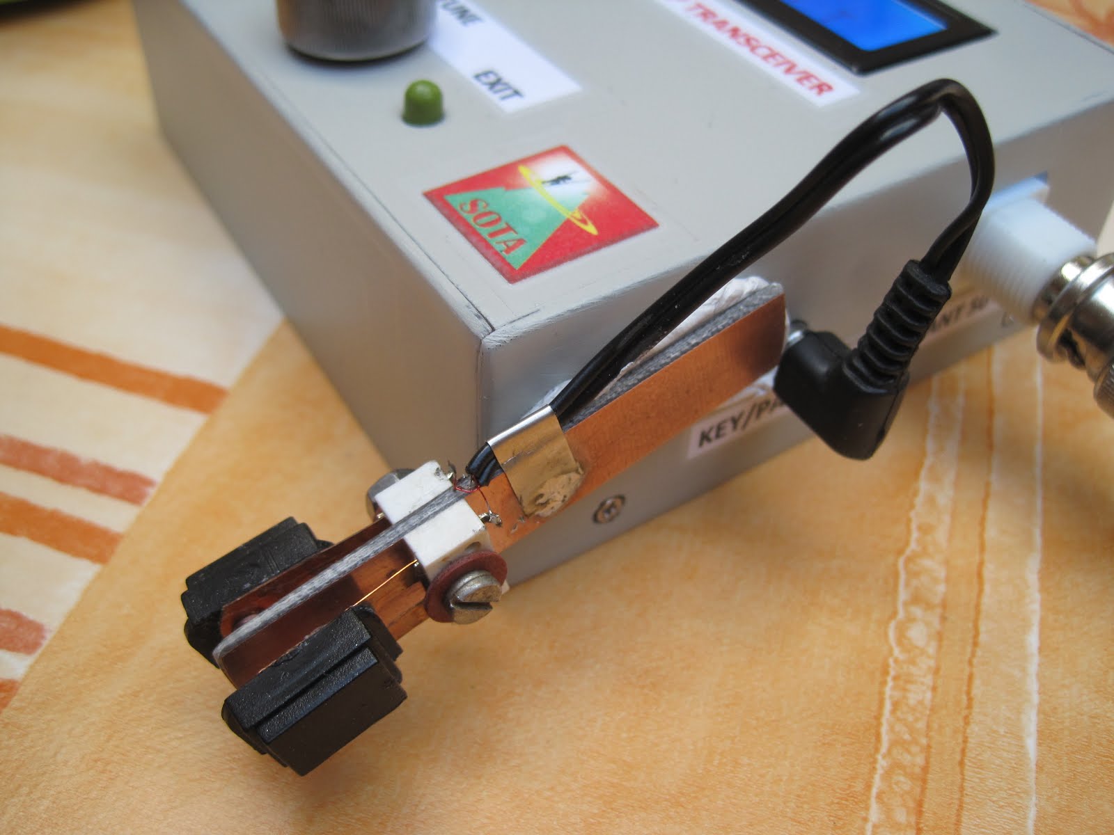
Then I also
needed a paddle ...
Again
inspired by the QRPGuys paddle in Ken’s document, I made a iambic paddle from
two relay contacts and four pieces of pcb, each 3cm x 1.3 cm.
The paddle just
sticks to the case with “blue tack” (although my blue tack is white, hi)

This paddle wheighs just 14 grams, including the cable and jack.
In a kind of competition with Ignacio EA2BD (see full story on the SOTA Reflector here ), I later made an even lighter version of this paddle, that was only 9 grams ! This one sticks to the side of the rig, close to the key/paddle connector.
Next
April/May I will be in EA8 Gran Canaria for some SOTA fun, if you hear me give
me a call …
UPDATE 1 : I did take the rig on one summit on Gran Canaria, and after spotting, I made 5 QSO's in just 4 minutes !
UPDATE 2 : In June 2018, I met Hans G0UPL in Friedrichshafen, and showed him my build.
He took some pictures and my rig features in the QRP Labs July 2018 newsletter, read it here
UPDATE 3 : The QCX has gone through several revisions, many of the mods that I mentioned are no longer needed. Make sure you download the correct assembly manual for your version.
UPDATE 4 : I removed the SOTA sticker and drilled a hole above the microswitch key, and glued a soft rubber "nipple" on it ... feels great when keying ! HI
So now it looks like this:

73,
Luc – ON7DQ
vy good job
ReplyDeleteQRP QCX also
Nice job, Luc!
ReplyDelete